ZIPped Project files (sch, pcb, symbols, footprints) (22 kb)
| www.delorie.com/electronics/m16c-26-adapter/ | search |
|
|
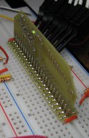
This was a weird idea I've had for a while. I've built a couple of
DIP adapters (r8c/27, r8c/1b, and cpld) for my solderless breadboard, but they
always end up wide enough to cover up many of the wire holes. This
one is vertical, so the footprint is only as wide as a standard 0.3
inch DIP.
ZIPped Project files (sch, pcb, symbols, footprints) (22 kb) |
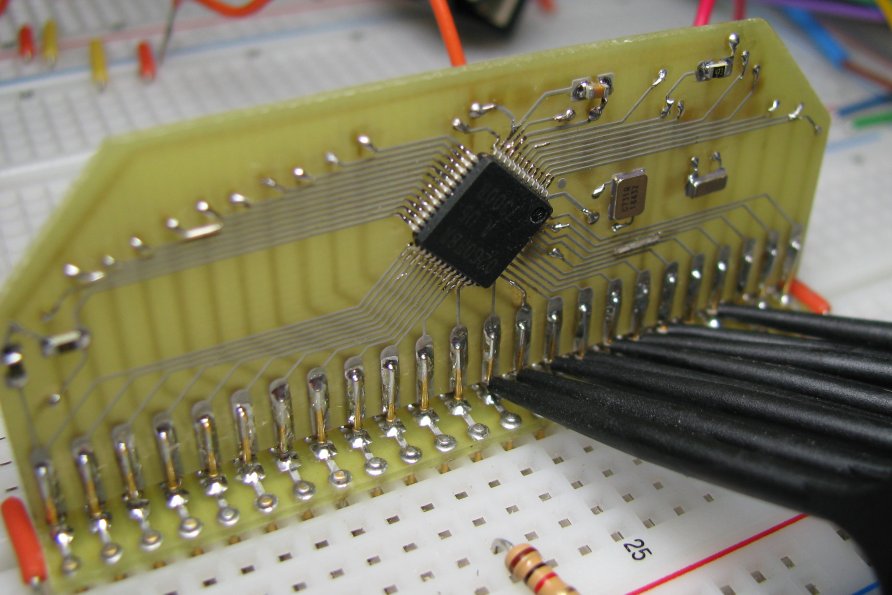
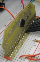
| Close-up of the chip side of the riser. All pins are brought out to the breadboard, but some common support circuits are also included: 18.432 MHz main clock, 32,768 Hz secondary clock, I2C pullups, power bypass, RESET and CNVss keepers, and a power indicator. The eight probe clips are connected to the P10 GPIO pins. The board is mostly 8/8 rules with 12 mil traces where space permits, and the discretes are 0603. |
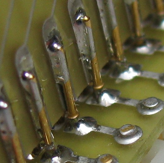
| Close-up of the riser pins. There are 96 press-fit pins (the gold-colored parts) for 48 pins. Since I build my own boards, I have to solder them - I don't have plated-though holes. The outer rows of pins go to the breadboard, and the inner rows go to the riser. A total of 240 solder joints, as the pins are connected both on top of and on the bottom of the small foot board, for strength. The riser is held up off the foot board enough to get my probe clips onto the pins. |
| webmaster | delorie software privacy |
| Copyright © 2008 | Updated Jul 2008 |