
| www.delorie.com/electronics/r8c-27-adapter/ | search |
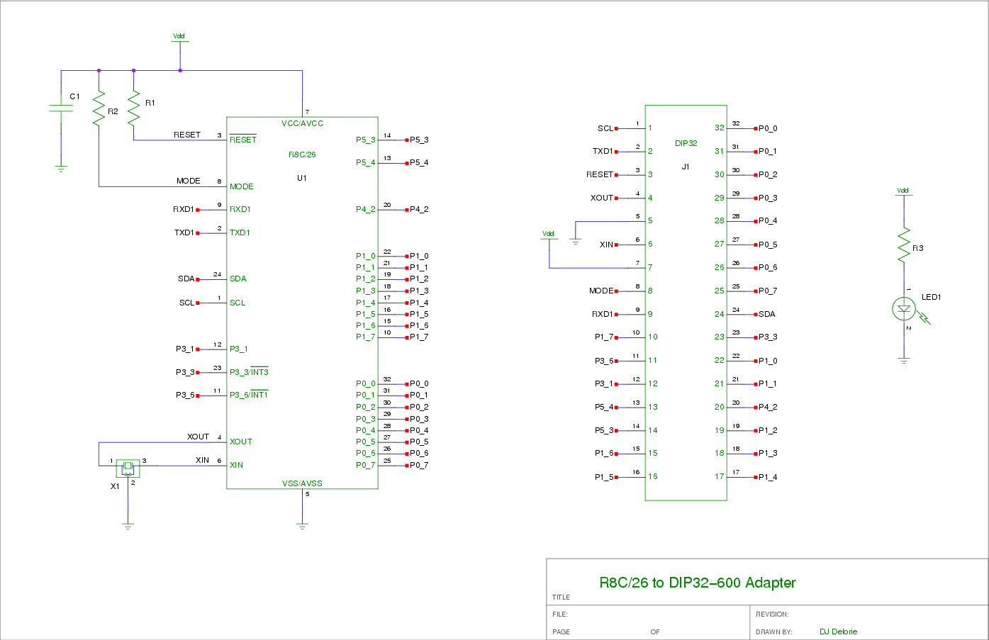
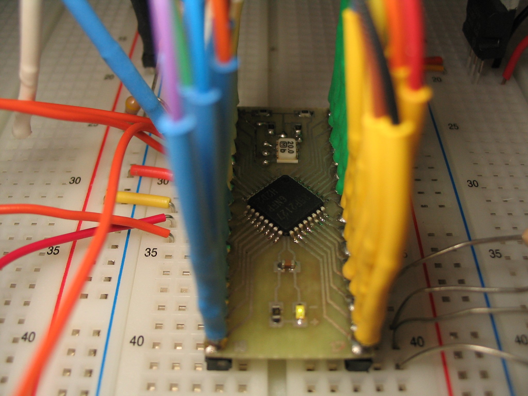
This is an adapter for R8C/27 TQFP-32 (0.8mm pitch) chips. It will accept R8C/26 also, of course, and maybe other R8Cs as long as the control/power pins are in the same place. The design includes i2c pullups, reset and mode pullups, and an oscillator, but of course you don't have to populate the parts you don't want. The R8C/13 family can be used, if you omit the i2c and mode pullups, and provide your own MODE/CNVss resistors. It can be built as a single-sided board if you don't mind a few jumpers.
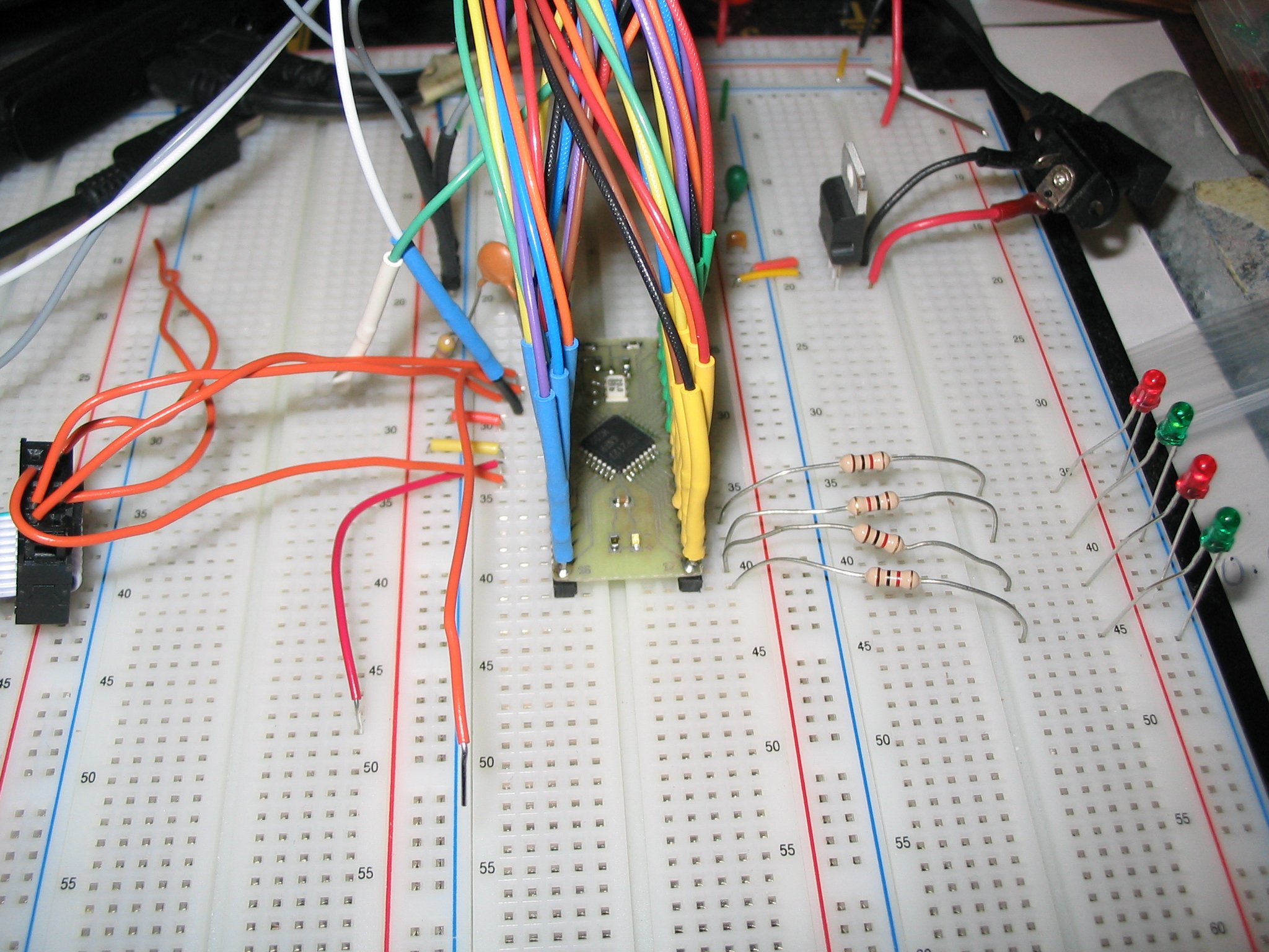

Note that a weak pull-up is required on pin 2 when using the ten-nine cable to program. The cap on reset is not required, I included it on the protoboard just because it gives cleaner edges for my logic analyzer when using the hand-reset wire. I have a loose wire for MODE and one for RESET, for use when programming.
A ready-for-print pinout table is available.
EDA tools used:

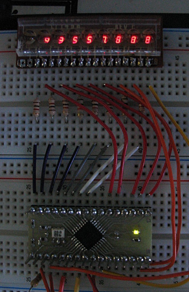
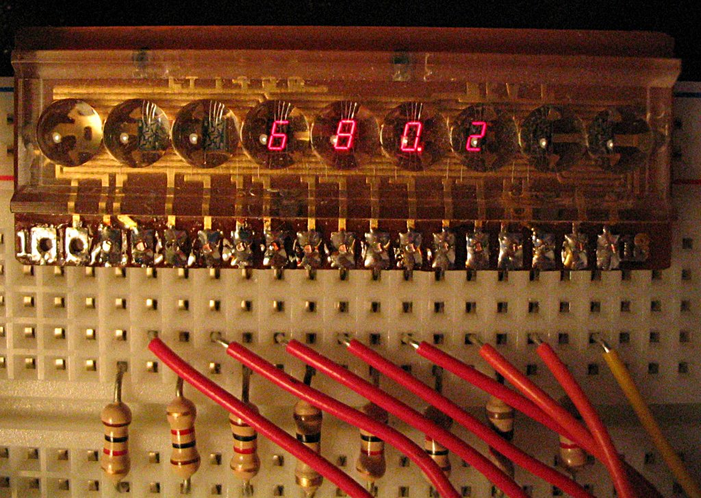
This is a simple project that used an old 8-digit calculator display I had in my parts cabinet. The R8C/27 has a high-current drive mode on P1, so I used that for the digit lines, and put P0 on the segment lines. That way, P0 only draws a few milliamps but P1 draws about 16 milliamps. Only one digit is on at a time, but all segments are on for that digit. You can see in the last photo how the scanning works; that was a 1/250 sec exposure. The scan is one digit per millisecond, so in four milliseconds four digits are lit.
The main source file shows how the timer interrupt is set up and how the scanning is done.
| webmaster | delorie software privacy |
| Copyright © 2007 | Updated Dec 2007 |